
INDUSTRIAL AUTOMATION
G9SA-301
Omron
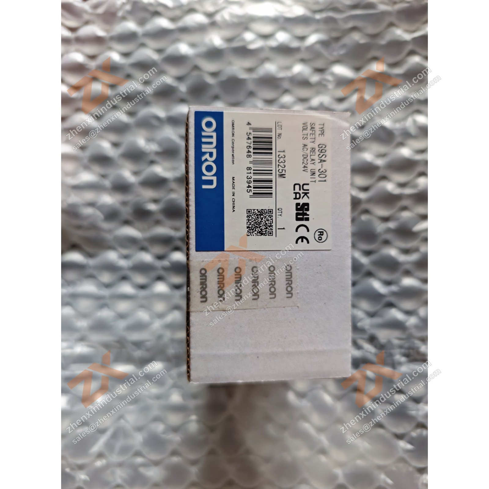
Omron G9SA-301. Reference photograph supplied by Zhenxin Industrial; the image may show the product, its nameplate or labelled packaging. Confirm the complete ordering code, revision, condition and required quantity before quotation.
This page identifies a sourcing reference. It does not guarantee continuous stock. Availability, condition, quantity, lead time, and commercial terms are confirmed after inquiry.
Copy the model and paste it into WhatsApp with your required quantity.
Reference details
- Manufacturer / brand
- Omron
- Model / reference
- G9SA-301
- Series / type
- Confirm against nameplate
- Condition
- Confirm with inquiry
- Quantity
- Confirm with inquiry
- Lead time
- Confirm with inquiry
Product information
Product Overview
A 3-pole safety relay unit with one auxiliary contact and one or two input channels, in a 45 mm-wide body. The G9SA is Omron’s compact safety relay for guarding circuits — E-stop, interlock and light curtain applications where a full safety controller would be over-specified.
This page is written for buyers and maintenance engineers sourcing G9SA-301 as a new part or a replacement. Every specification below is taken from Omron’s own published data for this model; no third-party or estimated figures are used, and where Omron publishes two different figures or two variants for the same parameter, both are shown.
Omron catalogue designation: G9SA safety relay unit. Official catalogue code for this model: G9SA-301.
Why Buyers Specify This Model
Three safety poles in a 45 mm body
3PST-NO main contacts plus an SPST-NC auxiliary for monitoring. Three safety poles is enough to isolate the three phases of a small drive, or to switch two separate load circuits and still have a pole for a feedback loop — at a width that does not force the panel to grow.
5,000,000 mechanical operations is the number that matters
Electrical contacts are rated 100,000 operations at the stated load, but the mechanical durability is 5,000,000 operations. On a guard door interlocked through a G9SA, the mechanical figure is what you are actually consuming — and it is why a dedicated safety relay outlasts a general-purpose relay used for the same duty.
Response time of 10 ms is part of the safety calculation
Omron publishes operating time (30 ms max.) and response time (10 ms max., the time for the main contact to open after the input is turned OFF). When a machine’s stopping-distance calculation includes the relay, this is the figure that goes into it. Take it from the datasheet, not from an assumption.
The auxiliary contact is for monitoring, not for load
Terminals 41-42 are the SPST-NC auxiliary. It is there to feed back the relay state to a PLC or to the safety circuit, not to switch the load. Confusing the two is a wiring error that defeats the monitoring function.
Expansion without changing the safety architecture
The G9SA-EX301 and G9SA-EX031-T@ Expansion Units connect to a G9SA-301. That lets a machine add more safety poles without adding a second safety relay and a second set of monitoring contacts — the expansion shares the parent unit’s state.
Technical Specifications (Official Omron Data)
| Parameter | Official value |
|---|---|
| Main contacts | 3PST-NO |
| Auxiliary contact | SPST-NC |
| Number of input channels | 1 channel or 2 channels possible |
| Rated voltage | 24 VAC/VDC or 100 to 240 VAC (specify when ordering) |
| Power supply voltage | 24 VAC, 50/60 Hz, or 24 VDC — 100 to 240 VAC, 50/60 Hz |
| Operating voltage range | 85% to 110% of rated power supply voltage |
| Power consumption | 24 VAC/VDC: 1.8 VA / 1.7 W max. 100 to 240 VAC: 9 VA max. (add 2 VA / 2 W max. when an Expansion Unit is connected) |
| Input current | 40 mA max. (increased by 30 mA max. when an Expansion Unit is connected) |
| Rated load | Resistive load — 250 VAC, 5 A; 30 VDC, 5 A |
| Rated carry current | 5 A |
| Contact resistance | 100 mΩ (measured with 1 A at 5 VDC by the voltage-drop method) |
| Operating time | 30 ms max. (not including bounce time) |
| Response time | 10 ms max. (time for the main contact to open after the input is turned OFF; includes bounce time) |
| Isolation voltage (Ui) | 250 VAC |
| Impulse withstand voltage (Uimp) | 4 kV |
| Insulation resistance | 100 MΩ min. at 500 VDC |
| Dielectric strength | 2,500 VAC for 1 min. between input and output, and between different poles of output |
| Vibration resistance | 10 to 55 to 10 Hz, 0.375 mm single amplitude (0.75 mm double amplitude) |
| Shock resistance | Destruction 300 m/s²; Malfunction 100 m/s² |
| Durability — mechanical | 5,000,000 operations min. (at approx. 7,200 operations/hr) |
| Durability — electrical | 100,000 operations min. (at approx. 1,800 operations/hr) |
| Failure rate (P level, reference) | 5 VDC, 1 mA |
| Ambient operating temperature | −25 to 55 °C (no icing or condensation) |
| Ambient operating humidity | 35% to 85% |
| Terminal tightening torque | 0.98 N·m |
| Weight | Approx. 210 g |
| Safety output terminals | 13-14, 23-24, 33-34 |
| Auxiliary contact terminals | 41-42 |
Available in two supply variants — 24 VAC/VDC and 100 to 240 VAC. Omron’s ordering information requires the power supply voltage to be specified when ordering; they are distinct catalogue entries and the power consumption differs substantially between them.
Lifecycle and availability
The G9SA is documented in Omron’s current safety relay unit datasheet, which carries the family ratings, characteristics, terminal assignments and dimension drawings for the G9SA-301 alongside the -501, -321-T@, -TH301 and the EX Expansion Units.
Safety relays are specified against a risk assessment, so the important thing is to supply the number the assessment was written around — same pole count, same supply voltage, same terminal arrangement. Send us the existing unit’s label or the machine’s safety documentation and we will confirm the number before quoting. If the original circuit had more poles than the -301 provides, tell us and we will price the -501 or an Expansion Unit rather than let the order go through short.
Availability, condition of supply and lead time are quoted per enquiry because they depend on quantity and on where the goods are held. We do not publish stock or lead time as fixed figures on this page. Tell us the quantity and the date you need it and we will answer with a firm position rather than a promise.
Official Documentation
The specifications on this page are taken from Omron’s own documents. You can download the source document directly:
- G9SA Safety Relay Unit Datasheet — https://edata.omron.com.au/eData/Safety/G9SA_DS.pdf
Full technical detail — wiring diagrams, derating curves, installation requirements and the complete ordering tables — is in that document. If you need a specific figure we do not show here, ask and we will point you to the exact page rather than paraphrase it.
Ordering This Part
Send us the full catalogue number G9SA-301 (and the model number G9SA-301 you are replacing), the quantity, your delivery address and the date you need the goods. If it is a replacement, attach a photograph of the existing unit’s nameplate — it removes any doubt about the revision, the output type or the supply voltage, which are the three things that most often cause a wrong part to be shipped.
We do not publish stock, condition or lead time as fixed figures here, because they change: they are quoted per enquiry against the quantity and date you actually need. If a machine is down, say so and give us the required window — that is the information that determines how we source it.
Frequently Asked Questions
24 VAC/VDC or 100 to 240 VAC?
Both are catalogue models and Omron asks for the supply voltage to be specified at ordering. The current draw differs: 1.8 VA / 1.7 W max. on 24 V against 9 VA max. on 100 to 240 VAC. State the panel supply when enquiring.
Can it take two input channels?
Yes — Omron’s data lists one channel or two channels as possible for the G9SA-301. Two-channel operation is the normal configuration for a dual-channel E-stop or interlock arrangement with cross-monitoring.
How does it compare with the G9SA-501?
The G9SA-301 has three main contacts (3PST-NO); the G9SA-501 has five (5PST-NO) and draws more current — 60 mA max. input current and 2.8 VA / 2.6 W max. on 24 V. The rest of the family ratings are the same. Choose by how many safety poles the circuit actually needs.
What are the terminal numbers?
Safety output contacts are 13-14, 23-24 and 33-34; the auxiliary contact is 41-42. Terminal T23 is used for 2-channel input with a positive common when connecting a safety sensor with a PNP output. Tighten terminals to 0.98 N·m.
MODEL INQUIRY
Request this
reference.
Include a nameplate photo or full specification when revisions may differ.